* Estimated delivery times start from the date of shipment, excluding processing time.
* Actual delivery times may vary due to holidays, weather conditions, or customs delays.
Envío estándar gratis en pedidos superiores a $9.9
Política de devolución
Los artículos devueltos serán aceptados dentro de los 40 días posteriores a la recepción de los productos. Los artículos personalizados no se pueden devolver ni cambiar. Los artículos comprados con una tarjeta de regalo electrónica solo son intercambiables; no se aplican reembolsos.
Regalo gratis
Bienvenido a Roymall, tu sitio web profesional para comprar regalos de tiendas departamentales premium. Valoramos y apreciamos mucho tu apoyo, y queremos expresar nuestra gratitud agregando un toque extra de emoción a tus compras. Cuando compras con nosotros, no solo disfrutas de productos de alta calidad que mejoran tu estilo de vida, sino que también recibirás un regalo exclusivo con cada pedido que realices. ¿Listo para explorar nuestra colección y encontrar tus regalos perfectos? Navega por nuestra selección de artículos de tiendas departamentales premium, realiza tu pedido y espera con ansias la emoción de recibir tu regalo gratis junto con tu compra.
Política de envío
Trabajaremos duro para entregarte los artículos después de recibir tus pedidos y asegurarnos de que lleguen de manera segura. Los detalles de entrega se proporcionarán en tu correo de confirmación.En la mayoría de los casos, los pedidos se procesan en 2 días. En circunstancias especiales, se retrasará de la siguiente manera: Cuando realices un pedido el sábado, domingo o días festivos, se retrasará 2 días.Normalmente, se necesitan de 5 a 7 días hábiles (de lunes a viernes) sin verse afectado por retrasos en los vuelos u otros factores ambientales.Debido a que nuestro servicio de envío es mundial, los tiempos de entrega dependerán de tu ubicación, por lo que puede tardar unos días y te pedimos paciencia si estás en distritos o países remotos.
1. Política de devolución y cambio
Solo aceptamos artículos comprados en roymall.com. Si compras a través de nuestros distribuidores locales u otros minoristas, no puedes devolverlos con nosotros.Los artículos de venta final o regalos gratuitos no son aceptables para devolución.Para ser elegible para una devolución, tu artículo debe estar sin usar y en las mismas condiciones en que lo recibiste. También debe estar en su empaque original.Después de recibir las instrucciones de devolución de nuestra parte, por favor empaqueta tus artículos devueltos y deja tu paquete en la oficina de correos local o en otro servicio de mensajería. Procesaremos tu devolución o cambio de artículo en un plazo de 3 a 5 días hábiles después de recibirlo. El reembolso se procesará y acreditará automáticamente en tu método de pago original.No se aceptan devoluciones ni cambios si el producto fue producido a medida, incluido tamaño personalizado, color personalizado o impresión personalizada.¿Necesitas más ayuda? Contáctanos. service@roymall.com o Whatsapp: +447549870296
2. Política de reembolso
Recibirás un reembolso completo o un crédito de tienda del 100% después de que recibamos y verifiquemos el paquete devuelto. El reembolso se procesará y acreditará automáticamente en tu método de pago original.Ten en cuenta que los costos de envío y cualquier impuesto o tarifa no son reembolsables. Los costos de envío adicionales no son reembolsables una vez que el paquete ha sido enviado. Eres responsable de pagar estas tarifas y no podemos exonerarlas ni reembolsarlas, incluso si el pedido nos es devuelto.Una vez que recibamos y confirmemos tu artículo devuelto, te enviaremos un correo electrónico para notificarte que hemos recibido tu artículo devuelto. También te notificaremos la aprobación o el rechazo de tu reembolso.Si tienes algún problema con el proceso de reembolso, contáctanos. service@roymall.com o Whatsapp: +447549870296
How to use one antenna at the same time for the radio and SDR:
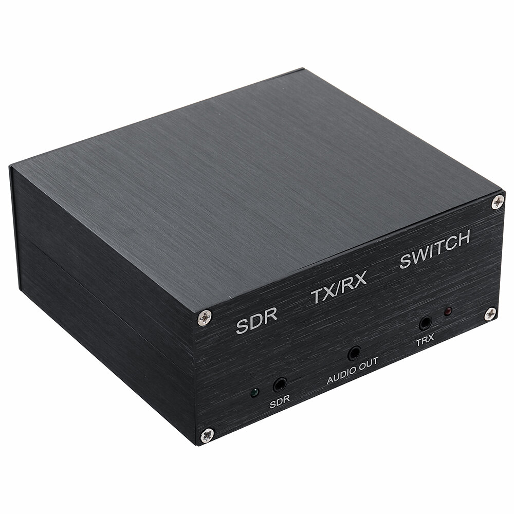
1. This sharer is a shared antenna between the radio and the SDR. After receiving the goods, open the box, remove the "jumper" in the middle, and change it to an automatic control state, that is: when the radio is transmitting, the SDR receiving channel is automatically closed, and the radio When not transmitting, the radio receives the signal together with the SDR.
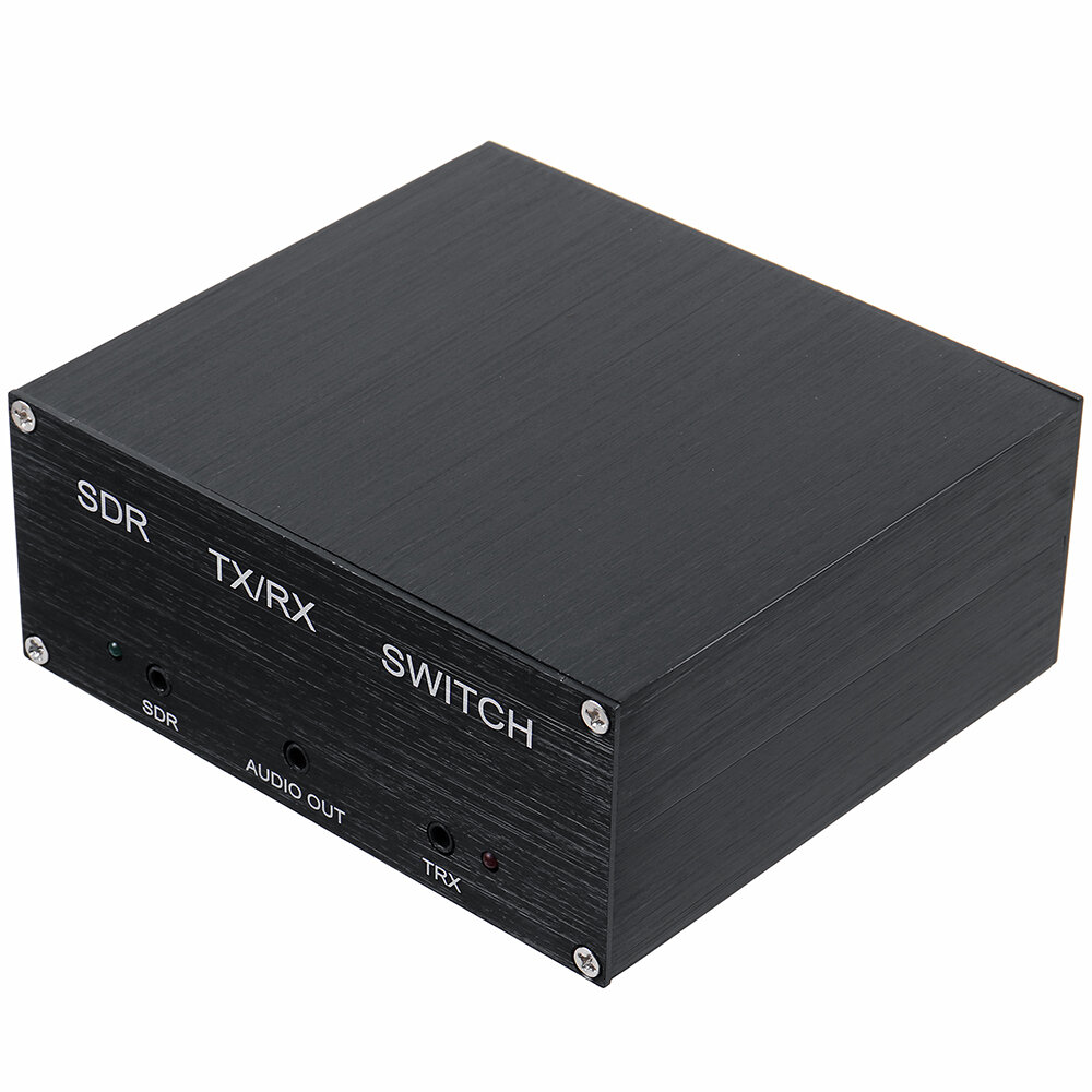
2. The jacks in front of the panel do not need to be wired, and the distributed PTT line does not need to be connected.
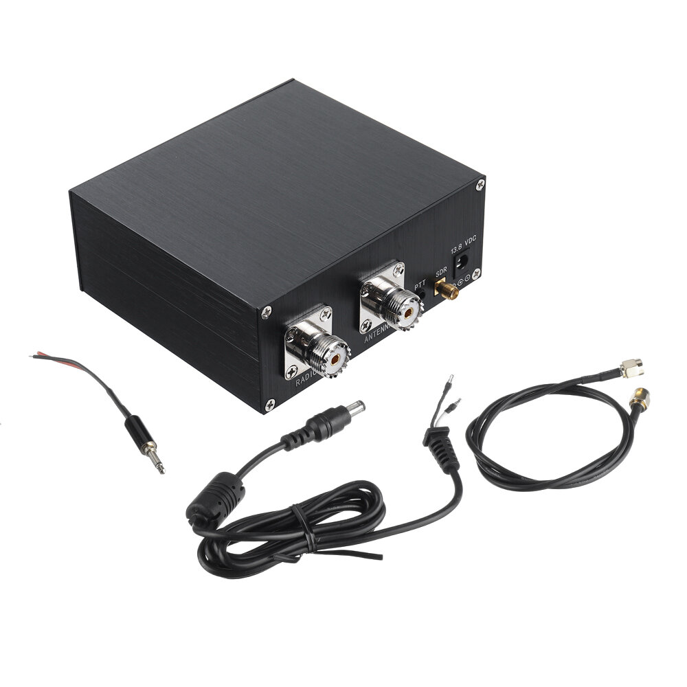
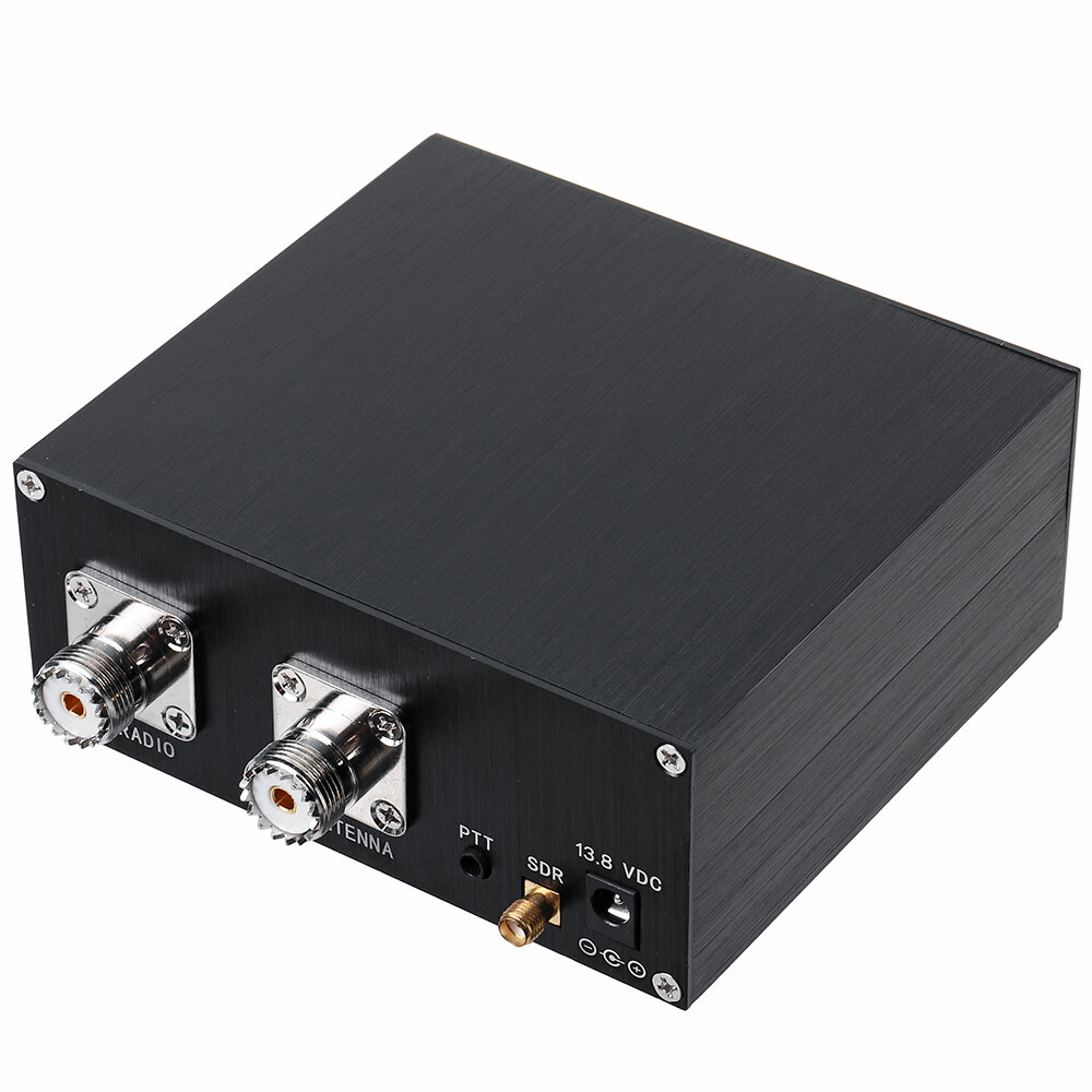
3. The rear jacks correspond to the power supply (VDC) interface, the radio (RADIO) interface, the SDR interface, and the antenna (ANTENNA) interface, respectively, and connect to the feeder according to each interface.
4. It is recommended to use the feeder with good shielding performance and cover it with a magnetic ring.
5. It is recommended that the sharer and the radio shell be grounded, because the radio may interfere with the SDR when transmitting.
6. After removing the jumper in the box, it is normal that the TRXlight on the panel is always on red; when the radio is not transmitting, the SDR on the panel is green and it is in normal working state; when the radio is transmitting, the SDR light on the panel will be off, and the SSB will follow the idea of communication. It is normal for the sound to change, the indicator light to flash and the relay to make a sound.
This is a very good panadapter switch so you can use your HF antenna (or upto 160Mhz) with your radio and your SDR receiver at the same time. This allows me to view a wide live bandscope on my computer using SDRUno and control the HF radio via Omnirig. To see this in action please search YouTube for Tech Minds.
This is a very good panadapter switch so you can use your HF antenna (or upto 160Mhz) with your radio and your SDR receiver at the same time. This allows me to view a wide live bandscope on my computer using SDRUno and control the HF radio via Omnirig. To see this in action please search YouTube for Tech Minds.
This is a very good panadapter switch so you can use your HF antenna (or upto 160Mhz) with your radio and your SDR receiver at the same time. This allows me to view a wide live bandscope on my computer using SDRUno and control the HF radio via Omnirig. To see this in action please search YouTube for Tech Minds.
arrived in about a week I moved the internal jumper to share the antenna. The device works perfectly. Sharing my DX Commander antenna with my Icom 706 transceiver and my SDRplay2. Now I have a waterfall display while using my old 706. Recommend this SDR Switch.
arrived in about a week I moved the internal jumper to share the antenna. The device works perfectly. Sharing my DX Commander antenna with my Icom 706 transceiver and my SDRplay2. Now I have a waterfall display while using my old 706. Recommend this SDR Switch.
arrived in about a week I moved the internal jumper to share the antenna. The device works perfectly. Sharing my DX Commander antenna with my Icom 706 transceiver and my SDRplay2. Now I have a waterfall display while using my old 706. Recommend this SDR Switch.
Tips:For questions about your order, place of delivery, product discount, taxation, delivery time, warranty, shipping, payment, exchange rate, and other questions unrelated to the product, please contact customer service.
showing 1-27 of 27|
Show Original
A part of the QA has been auto-translated.
0
Q:
The details sections says 100W output, but that's not possible with a power supply of 13.8V/200mA. Can anyone shed light on this?
The details sections says 100W output, but that's not possible with a power supply of 13.8V/200mA. Can anyone shed light on this?
It is 100W THROUGHPUT. 100W from transceiver out into the adapter and same 100W out to the antenna. Power supply (12V 200mA) only for internal circuitry (relay, switch, whatever is inside) 100W means you can not use with linear amplifier (500W-1kW)
It is 100W THROUGHPUT. 100W from transceiver out into the adapter and same 100W out to the antenna. Power supply (12V 200mA) only for internal circuitry (relay, switch, whatever is inside) 100W means you can not use with linear amplifier (500W-1kW)
Answered by es2dc on 13/04/2021Helpful (0)
0
Q:
The Specification is DC-160mhz. My unit will NOT perform above 50mhz -VERY high SWR.?
The Specification is DC-160mhz. My unit will NOT perform above 50mhz -VERY high SWR.?
trychanging internal jumper, if radio has a ppt socket 2x3.5mm plug it in both terminals the it switches as soon as you key
trychanging internal jumper, if radio has a ppt socket 2x3.5mm plug it in both terminals the it switches as soon as you key
Answered by SIFFLER on 24/01/2025Helpful (0)
0
Q:
Received my switch. When hooked up as required, I get a strong antenna signal at my SDR, but no antenna signal at the radio? I have tried two different coax patch cables from the switch to the radio with same results. Not just a bad signal, NO signal at the radio.
Received my switch. When hooked up as required, I get a strong antenna signal at my SDR, but no antenna signal at the radio? I have tried two different coax patch cables from the switch to the radio with same results. Not just a bad signal, NO signal at the radio.
Use a filter for interference , as the unit is only for displaying your tx through an SDR program, including.. Seeing other hams tx signals on the band, by use of your SDR programmes waterfall. And what ever you wish to qrp or not, the HF band your wanting to chase, including , monitoring your own TX, for other purposes.
Use a filter for interference , as the unit is only for displaying your tx through an SDR program, including.. Seeing other hams tx signals on the band, by use of your SDR programmes waterfall. And what ever you wish to qrp or not, the HF band your wanting to chase, including , monitoring your own TX, for other purposes.
Answered by B on 11/04/2022Helpful (0)
0
Q:
The device is working fine. I purchased it a few months back. But, I would like to learn more about the function and purpose of the three additional 3.5 mm jacks located on the opposite side of the device from where the two PL259 and SMA connections are located. The jacks are Labeled: J1 TRX, J2 AUDIO OUT, J3 SDR. Is there any available documentation which has the descriptions of these jacks? Best Regards, Thank You
The device is working fine. I purchased it a few months back. But, I would like to learn more about the function and purpose of the three additional 3.5 mm jacks located on the opposite side of the device from where the two PL259 and SMA connections are located. The jacks are Labeled: J1 TRX, J2 AUDIO OUT, J3 SDR. Is there any available documentation which has the descriptions of these jacks? Best Regards, Thank You
12V should be fine. It's close enough to 13.8V to still operate. It's probably a 12V circuit and just shown as 13.8V because that's the most common voltage used to power transceivers.
12V should be fine. It's close enough to 13.8V to still operate. It's probably a 12V circuit and just shown as 13.8V because that's the most common voltage used to power transceivers.
Answered by BG101216243 on 17/07/2021Helpful (0)
0
Q:
Is there some user/instruction manual available for this switching box please.... I am getting loads of feedback between my sdr and the radio when I try transmitting and also the relay is clicking like mad between tx to sdr when trying to transmit on ssb
Is there some user/instruction manual available for this switching box please.... I am getting loads of feedback between my sdr and the radio when I try transmitting and also the relay is clicking like mad between tx to sdr when trying to transmit on ssb
personally, I have a very bad experience with it. The seller declares use up to 160Mhz and that is misleading the customer. .It is usable up to 30 MHz, but for example already at 144 MHz it has an SWR of 1:10 !! and that is unacceptable
personally, I have a very bad experience with it. The seller declares use up to 160Mhz and that is misleading the customer. .It is usable up to 30 MHz, but for example already at 144 MHz it has an SWR of 1:10 !! and that is unacceptable
When I turn on the power on this device on the HF radio and SDR there is no signal. But at the VHF/UHF frequency when the power is turned on the radio there is radio signal and sound. Where's the problem ?
When I turn on the power on this device on the HF radio and SDR there is no signal. But at the VHF/UHF frequency when the power is turned on the radio there is radio signal and sound. Where's the problem ?
My guess - VHF and UHF are nor filtered by switch and goes through while HF is filtered by internal circuit. Open your SDR switch and try to move short black jumper to other position then it is now. Hope this helps
My guess - VHF and UHF are nor filtered by switch and goes through while HF is filtered by internal circuit. Open your SDR switch and try to move short black jumper to other position then it is now. Hope this helps
Answered by LY4SA on 26/06/2023Helpful (0)
0
Q:
Dear Eric, Thanks for the reply but I was referring to the udated QRM Eliminator version with TX RED Indicator when PTT works. See Aliexpress please.
Dear Eric, Thanks for the reply but I was referring to the udated QRM Eliminator version with TX RED Indicator when PTT works. See Aliexpress please.
Do you mean this item?> https://www.banggood.com/QRM-Eliminator-X-Phase-(1-30-MHz)-HF-Bands-Box-p-1828030.html?rmmds=detail-topright-recommendation&cur_warehouse=CZ&trace_id=19ee1657942637045
Do you mean this item?> https://www.banggood.com/QRM-Eliminator-X-Phase-(1-30-MHz)-HF-Bands-Box-p-1828030.html?rmmds=detail-topright-recommendation&cur_warehouse=CZ&trace_id=19ee1657942637045
Answered by Eric on 15/07/2022Helpful (0)
0
Q:
I am not able to pass 100w on all bands. 10m is only 40w, 6m is 20w, and 2m is 5w. Am I doing something wrong? SWR is just fine.
I am not able to pass 100w on all bands. 10m is only 40w, 6m is 20w, and 2m is 5w. Am I doing something wrong? SWR is just fine.
There are no instructions how to connect the 3.5 mm jack to a Yaesu FT991A 8-pin DIN breakout cable Sandy. Please show wiring diagram or where in the instructions it can be found.
There are no instructions how to connect the 3.5 mm jack to a Yaesu FT991A 8-pin DIN breakout cable Sandy. Please show wiring diagram or where in the instructions it can be found.
It seems that safest thing to do is also connect the PTT lead, my PTT connection is a standard 3.5mm 2 terminal jack, I already have a 2 x 3.5mm jack lead could I use that rather than wire up the supplied lead with another 3.5mm jack?
It seems that safest thing to do is also connect the PTT lead, my PTT connection is a standard 3.5mm 2 terminal jack, I already have a 2 x 3.5mm jack lead could I use that rather than wire up the supplied lead with another 3.5mm jack?
Follow Up, About the 3 jacks: J1 SDR , J2 AUDIO, J3 TRX These jacks all appear to be 3.5 mm commonly used for speakers / audio. Question: Is J1 (SDR) jack for input of sound to the box? Question: Is J2 (AUDIO) for output of that signal to speakers? Question: Is J3 (TRX) for a switch to control signal from J1 to J2? Question: Are these Stereo (3 connections) on jack, or mono (2 connections)
Follow Up, About the 3 jacks: J1 SDR , J2 AUDIO, J3 TRX These jacks all appear to be 3.5 mm commonly used for speakers / audio. Question: Is J1 (SDR) jack for input of sound to the box? Question: Is J2 (AUDIO) for output of that signal to speakers? Question: Is J3 (TRX) for a switch to control signal from J1 to J2? Question: Are these Stereo (3 connections) on jack, or mono (2 connections)
Hello, I appreciate your answer regarding the purpose of the 3 jacks. But, I am confused by the answer. The SDR is connected to the USB port on the computer. The receive audio is created within the computer, and is routed directly to the speakers attached to the computer. I don't see how that audio signal could exist within the antenna switch. I mean the antenna connections PL259 in and PL259 out, and the SMA connection are not yet audio, until those signals have been processed by the SDR and computer, and the transceiver. So, perhaps one or more of the jacks are inputs for audio? Clarification would be appreciated. Best Regards, Thank you
Hello, I appreciate your answer regarding the purpose of the 3 jacks. But, I am confused by the answer. The SDR is connected to the USB port on the computer. The receive audio is created within the computer, and is routed directly to the speakers attached to the computer. I don't see how that audio signal could exist within the antenna switch. I mean the antenna connections PL259 in and PL259 out, and the SMA connection are not yet audio, until those signals have been processed by the SDR and computer, and the transceiver. So, perhaps one or more of the jacks are inputs for audio? Clarification would be appreciated. Best Regards, Thank you






 Direct purchase from the factory

![[US DIRECT] ATOMSTACK A5 M50 APP Control Dual-Laser Laser Engraving Cutting Machine Laser Engraver Cutter 5.5W Output Power Fixed-Focus 304 Mirror Stainless Steel Engraving DIY Laser Marking for Metal Wood Leather Vinyl](https://static.roymall.com/d/file/mall/titlepic/235/67803406-41f3-499a-afb7-154990584ff8.jpg?x-oss-process=image/resize,w_237/quality,Q_80/format,webp)

![[EU/US Direct]Raiser for LONGER RAY5 Engraver](https://static.roymall.com/d/file/mall/bigpic/235/65e9b76d-574a-4b4b-9c6c-02db18b89460.jpg?x-oss-process=image/resize,w_237/quality,Q_80/format,webp)
![[US/UK Direct] Refurbished ULTIMEA Nova S70 3.1.2 Soundbar 390W True Dolby Atmos Soundbar BassMax 4K Dolby Vision HDR Passthrough 3EQ Modes Wired Speaker Subwoofer](https://static.roymall.com/d/file/mall/titlepic/235/e1440062-c78c-4565-8aa7-f8857d749771.jpg?x-oss-process=image/resize,w_237/quality,Q_80/format,webp)
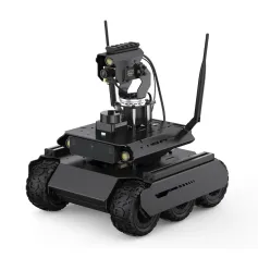







 Multi Rotor Parts
 Regalo gratis
 Política de envío
 Política de devolución